產(chǎn)品分類
售后服務(wù):400-086-1088
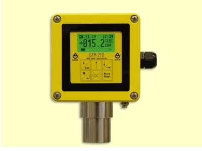
Gas transmitter - ADOS GTR 210
Available basic versions:
– Ex-version: with current interface 4-20 mA
– Standard: 4-20 mA or LON?-4-wire techniques
– Comfort: 4-20 mA, with additional changeover contacts for alarms and failure
The type test of the explosion-protected gas transmitter, is completed by the KEMA.
ATEX certificate: DEKRA 11ATEX0257 X
IECEx certificate: IECEx DEK 11.0090X
Type of protection: Ex d e ia mb IIC T4 Gb
- 技術(shù)參數(shù)
- 產(chǎn)品特點
- 應(yīng)用領(lǐng)域
- 資料下載
| Type | TGS | VQ | GOW |
|---|---|---|---|
| Measurement method | Semiconductor | Heat reduction | Thermal conductivity |
| Measurement range | ppm ranges to 100 % LEL |
ppm ranges to 100 % LEL |
from 0-5 Vol% to 0–100 Vol % |
| Percentage error of f.s.d. |
±5 % | ±3 % | ±5 % |
| Temperature range | -25 °C to +55 °C | -25 °C to +55 °C | -25 °C to +55 °C |
| Temperature effect | 3 % | 2 % | 3 % |
| Response time (t90) | approx. 55 s | approx. 40 s | approx. 55 s |
| Pressure effect | 1 % | 1 % | 1 % |
| Mounting position | optional | optional | optional |
| Application | Poisonous, combustible and explosive gases in the LEL?region |
Poisonous, combustible and explosive gases in the LEL?region |
Gases exhibiting substantial differences in thermal conductivity, compared to air |
| Versions available | industrial (Al), industrial (VA)- and Ex-version |
industrial (Al), industrial (VA)- and Ex-version |
industrial (Al), industrial (VA)- and Ex-version |
| Expected lifetime of the sensor |
unlimited, when used for gases not causing catalytic poisoning |
unlimited, when used for gases not causing catalytic poisoning |
unlimited, when used with gases that do not attack aluminium, rhenium-tungsten or gold |
| Dimensions (W x H x D) |
150 x 175 x 105 mm | 150 x 175 x 105 mm | 150 x 175 x 105 mm |
| Type | TOX | IR | PID |
|---|---|---|---|
| Measurement method | Electro-chemical reaction | Infrared | Photo-Ionisation |
| Measurement range | ppm ranges to 0–100 Vol % |
0-100 % LEL CH4, C3H8, C2H2, 0-100 Vol % CH4 0 –1, 2, 3, 4, 5 Vol % CO2 |
0 – 200 ppm to 0 – 2.000 ppm |
| Percentage error of f.s.d. | ±3 % | ±2 % | ±5 % |
| Temperature range | -25 °C to +55 °C | -25 °C to +55 °C | -25 °C to +55 °C |
| Temperature effect | 2 % | 2 % | 3 % |
| Response time (t90) | approx. 60 s | approx. 45 s | approx. 120 s |
| Pressure effect | 1 % | 4 % | 1 % |
| Mounting position | optional | optional | optional |
| Application | O2, CO, NH3, NO2, SO2, H2S and others | CH4 (Vol %; LEL) Propan (LEL), CO2 (Vol %) | e.g. C7H8, C8H10 CHCl3, PH3 |
| Versions available | industrial (Al), industrial (VA)- and Ex-version |
industrial (Al), industrial (VA)- and Ex-version |
industrial (Al), industrial (VA)- and Ex-version |
| Expected lifetime of the sensor |
12 months to 5 years depending on the measuring cell |
approx. 5 years | 12 months |
| Dimensions (WxHxD) | 150 x 175 x 105 mm 150 x 200 x 105 mm (O2) |
150 x 175 x 105 mm | 150 x 175 x 105 mm |
Technical data – for all 3 basic versions of gas transmitter
| Type | GTR 210 Ex-Version | GTR 210 Standard | GTR 210 Comfort |
|---|---|---|---|
| Supply voltage | 24 V DC +10% / -25% | 24 V DC +10% / -25% | 230 V AC, 50 Hz 115 V AC, 60 Hz (optional) |
| Power consumption | 4 W | 4 W | 10 VA |
| Interface | 3-wire techniques with current interface 4 – 20 mA | 3-wire techniques with current interface 4 – 20 mA or LON®-4-wire techniques | 1 current output 4 – 20 mA 4 potential-free changeover contact for alarm/failure 1 digital input for cancelling alarms |
| Type of protection | II 2G Ex d e ia mb IIC T4 Gb |
none | none |
| Ex-version | ATEX certificate: DEKRA 11 ATEX 0257 X IECEx certificate: IECEx DEK 11.0090 X |
||
| Protection class | IP 54 | IP 54 | IP 54 |
| Weight | 2,3 kg | 1,8 kg | 2,0 kg |
By employing 6 different types of sensor, noxious, explosive and non-combustible gases and vapours can be measured.
Display of the measured gas concentration and the adjustable alarm thresholds, are shown on a multi-colour graphic display. The keyboard input is by way of a touchpad.
A current signal is generated that is proportional to the measured concentration of gas, which is transmitted to an evaluation unit placed in a safe area, away from any dangers of explosion.
TOX sensor
The TOX sensor is a measurement system with electro-chemical cell, where the sampled gas is measured by diffusion. In the case of oxygen measurement the oxygen content is in an electrolyte, thus producing a small flow of current (electro-chemical process).
At a constant air pressure, this current is directly proportional to the oxygen concentration in the sampled air.

1 = Anode
2 = Electrolyte
3 = Cathode
4 = Diffusion path
5 = Diffusion filter
6 = Test gas
TGS sensor
The TGS sensor contains a semiconductor sensor, which is constructed on SnO2-sintered N-substrate.
When combustible or reducing gases are absorbed by the surface of the sensor, the concentration of the test gas is determined by the change in conductivity.

1 = Circuit voltage
2 = Heating voltage
3 = Load resistor
The IR sensor
The test gas flows through a measurement chamber that incorporates an IR radiating source and a two-channel
infrared detector. The intensitiy of the infrared radiation is reduced as it passes through the gas molecules.The concentration of the gas can then be calculated by the magnitude of the reduction in intensity.
Since only absorption of the wavelength specific to the gas under test in relation to the wavelength not absorbed by a test gas is considered, interference due to dust, ageing etc., is almost compensated.

1 = Infrared-radiating source
2 = Test gas
3 = Diffusion filter
4 = Infrared-detector
5 = Measurement chamber
GOW sensor
The GOW sensor functions on the principle of thermal conductivity. Two rhenium-tungsten resistors are used as a measuring element, where the comparison element is subjected to normal ambient air and the measuring element is subjected to the test gas. Any change in the concentration of gas at the measurement element, causes a change in temperature, which is due to the variation of conductivity.
The resultant change in resistance is a direct measure of the gas concentration.

1 = Diffusion filter
2 = Test resistor
3 = Comparsion resistor
The PID sensor
The sampled gas flows through a measurement chamber, that incorporates a UV radiating source and a pair of
electrodes with opposing polarity. The gas molecules to be detected are ionized by the UV radiation.
The resulting positively charged molecules and the electrons are attracted to the relevant electrode. The current generated is a measure of the gas concentration.
Using the PID measuring head, volatile organic compounds (VOC) can be measured, the ionisation potential of which is less than the energy in the UV radiating source (10,6 eV), e.g. aromatic hydrocarbons like toluol (C7H8) and xylene (C8H10) as well as chlorinated hydrocarbons like trichloroethylene (CHCl3). The detection of toxic gases like phosphine (PH3) is also possible.

1 = UV radiating source
2 = Test gas
3 = Capacitive charge
VQ sensor
The head of the VQ sensor functions on the principle of heat reaction. When combustible or reducing gases or vapours come in contact with the measuring element, they are subjected to catalytic combustion, which causes a rise in temperature; this rise causes a change in the resistance of the measuring element which is used as a measure of the component of gas being tested.
The inert element is for compensating the temperature and conductivity of the test gas.

1 = Catalyzer pellistor
2 = Electric connections
3 = Inert pellistor
4 = Diffusion filter
- Chemical industry
- Manufacture of paints and varnishes
- Plastics processing plants
- Sewage works
- Gas-fired boiler systems
- Liquid gas storage houses
- Laboratories
- Oxygen concentration measurements
- Refineries
- Cold storage houses (Ammonia monitoring)
- Paint spraying booths
- ... and many more.
